When Battle Royale meets 8-bit.4.
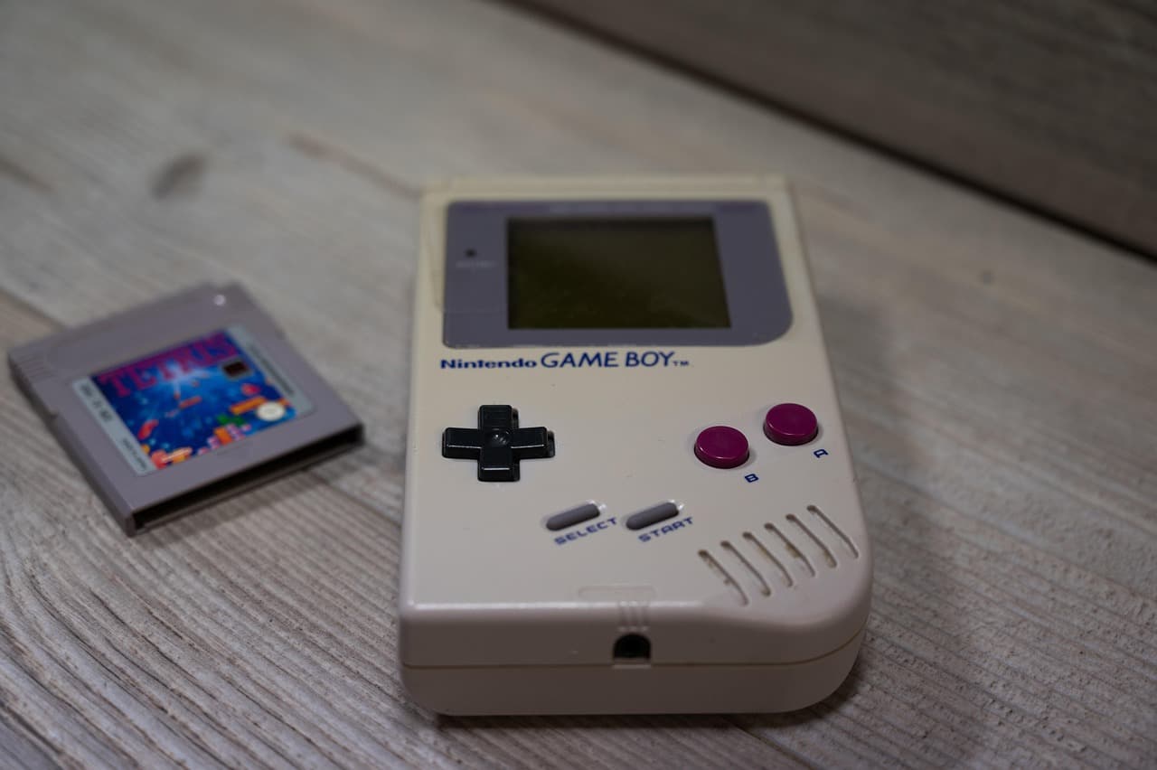
This project is a daring attempt to bring the spirit of modern battle royale games (like PUBG and Fortnite) to the world of the old Game Boy Color. Yes, you heard right – 160×144 pixels, 8-bit graphics, 4 channels of sound… and it all works!
What’s implemented:
- A map with a constriction zone – just like in the real Battlegrounds.
- Characters, weapons and battle mechanics – taking into account the limitations of the platform.
- Primitive AI enemies and survival mode.
- The visual style is strictly in the spirit of 90s games.
- ROM can be run on real hardware via cartridge or in an emulator.
Technical features:
- Written in Assembly and C using GBDK (Game Boy Development Kit).
- Graphics are hand drawn in 2D editor, adapted to the GBC palette.
- Optimized for the extremely limited memory and clock speed of the Game Boy Color.
- Tested on emulator and real console.
Why it’s done:
The project is a challenge to itself and the industry. The author wanted to prove that even a minimalistic gaming platform can capture the essence of the battle royale genre. It’s not just a port, it’s a remake with respect for the classics and a great knowledge of the limitations of the hardwar environment.
Who this project is for:
- Fans of retro gaming and the Game Boy;
- Developers interested in low-level programming;
- Fans of game genres and non-standard adaptations;
- Anyone who enjoys creative technical experiments.
- Why it’s on TorcA314:
Because that’s the spirit of the DIY movement – doing the impossible on a platform that’s long since been written off. This is a story about perseverance, craftsmanship and love of technology.